Three instruments compose the core payload of the mission: a microwave imager, a microwave water vapor sounder, a radiative budget radiometer. Preliminary studies have defined the main characteristics of these instruments. Their overall spectral characteristics are given below:
MADRAS
MADRAS (Microwave Analysis and Detection of Rain and Atmospheric Systems) is a microwave imager, with conical scanning (incidence angle 56°), close from the SSM/I and TMI concepts. The main aim of the mission being the study of cloud systems, a frequency has been added (157 Ghz) in order to study the high level ice clouds associated with the convective systems, and to serve as a window channel relative to the sounding instrument at 183 GHz.
| Frequencies | Polarization | Pixel size | Main use |
| 18.7 Ghz ± 100 Mhz | H + V | 40 km | ocean rain and surface wind |
| 23.8 Ghz ± 200 Mhz | V | 40 km | integrated water vapor |
| 36.5 Ghz ± 500 Mhz | H + V | 40 km | cloud liquid water |
| 89 Ghz ± 1350 Mhz | H + V | 10 km | convective rain areas |
| 157 Ghz ± 1350 Mhz | H + V | 6 km | cloud top ice |
Table 1 : main characteristics of the MADRAS channels
The main uses given here are only indicative, most of the products being extracted from algorithms combining the different channels information. The resolutions are those expected in the different channels, accounting for the specification of 10 km given for the 89 Ghz channel.
SAPHIR
SAPHIR (Sondeur Atmosphérique du Profil d’Humidité Intertropicale par Radiométrie) is a sounding instrument with 6 channels near the absorption band of water vapor at 183 Ghz. These channels provide relatively narrow weighting functions from the surface to about 10 km, allowing retrieving water vapor profiles in the cloud free troposphere. The scanning is cross-track, up to an incidence angle of 50°. The resolution at nadir is of 10 km.
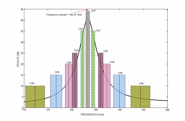
Figure 1 : The 6 channels of SAPHIR positioned versus the water vapour absorption line at 183,31 Ghz.
| Channels | Central Frequencies | Channel bandwith |
| S1 | 183.31 +/- 0.2 GHz | 200 MHz |
| S2 | 183.31 +/- 1.1 GHz | 350 MHz |
| S3 | 183.31 +/- 2.8 GHz | 500 MHz |
| S4 | 183.31 +/- 4.2 GHz | 700 MHz |
| S5 | 183.31 +/- 6.8 GHz | 1200 MHz |
| S6 | 183.31 +/- 11 GHz | 2000 MHz |
Table 2: SAPHIR channels
ScaRaB
ScaRaB (Scanner for Radiation Budget) is an optical scanning radiometer devoted to the measurements of radiative fluxes at the top-of-atmosphere (TOA) in the shortwave and longwave domain.
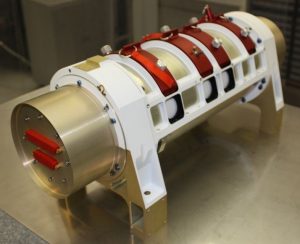
The optical radiometer is composed of 4 parallel and independent telescopes focusing the reflected solar and emitted thermal radiation of the earth atmosphere on 4 detection channels with high absolute accuracy (1%-2%) owing to onboard calibration modules.
| Wavelength | Channel |
| 1-Visible | 0.55-0.65 µm |
| 2-Solar | 0.2-4 µm |
| 3-Solar | 0.2-100 µm |
| 4-IR Window | 10.5-12.5 µm |